Resistors, Transformers, Capacitors for Tube Amps
- The Ingredients -(電子部品真空管アンプ | 電子元件电子管放大器)
Anode Resistor
The anode resistor practically resides directly in the signal path. Because of the changes in the anode current of the tube at this resistor results a voltage drop, which indeed is the amplified voltage that is taken with the coupling-capacitor.This means the selection of the anode resistor greatly influences the sound of the pre-amplifier. This goes for the values as well as for type.
Regarding the power-rating, usually 1 or 2 watts types are sufficient. Only if you use tubes with a high bias current - like the 417A/5842 - you should rather go for a 5 watts type.
Here you can “play the whole field” and try out all possible types, like metal film, tantalum or carbon resistors. But careful with old carbon resistors - they often cause a noise. An insider tip: use the Vishay Bulk-Foil VTA 52 types. Unfortunately no longer produced...
Before you spend your money on expensive coupling capacitors, you can achieve a better sound much cheaper with good anode resistors.
Cathode Resistor
The choice of the design type of the cathode resistor and the cathode capacitor has little effect on the sound. Interesting in this context is only the question whether you should use a cathode capacitor at all - or rather not. A cathode capacitor eliminates the current feedback via the cathode resistor for the applied signal voltage. This makes for a stronger amplification.Transformers
As soon as you have installed the transformers, you can’t exchange them as easily as a small anode resistor. Often you simply have to speculate whether your amplifier will work better with a new Sowter, Lundahl or Tango or the “historic” UTC, Western Electric or Thordarson transformer. Most of all, transformers aren’t easy to come by. So often it is a better choice to simply use an existing transformer as your base and then select a fitting tube (internal resistance, bias current).With end triodes the amplification loss is often too high when you don’t use a cathode capacitor. For the pre-amps you can simply install a switch to switch the capacitors on or off. Only when the amplifier is switched off, of course... This is an easy way to change the sound characteristics of an amplifier.
Capacitors
Capacitors are needed here:- As charging and filter capacitors in the power supply
- As coupling capacitors in the signal path (cout)
- As cathode capacitors
Always worth a try is arranging a bypass capacitors parallel, coupling a “big” with a “small” capacitor. The small capacitor should have approx. 0.5 to 1% of the capacity of the big capacitor.
Which means, for example, the parallel soldering of a 100uF electrolytic capacitor and a 0,68uF MKP. Whether this is useful with a beautiful old Bosch MP oil paper capacitor, though, you simply have to find out yourself by testing.
For cathode capacitors you don’t have to put in that much effort. More important for the pre-amp circuits we are talking about here is whether you are using a cathode capacitor at all. Which means you can easily use the handy tiny electrolytic capacitors.
The coupling capacitors can then again cause some headache. The capacity has to be carefully selected.. The cutoff frequency, still to be transferred, depends on this. The formula:
fu = 1 / (2 x pi x R x C) respectively C = 1 / (2 x pi x R x fu)
R is the input resistance of the following stage, so for a tube level usually the following grid-resistor, and fu is the cutoff frequency.
The principle: the bigger the capacitor, the lower the frequencies the amplifier can transmit. On the one hand you don’t want to lose any bass, of course. On the other hand, though, you won’t want low frequency vibrations below 5-10Hz either.
The capacity determines the rise time (T) of the capacitor as well. Rise time is the time the capacitor needs for changing with AC.
The formula:
T = RA x C
RA is the upstream anode resistor. You will want a “fast” amplifier. Which means that coupling capacitor (and anode resistor!) mustn’t be too big.
You can influence the sound characteristics of the amplifier by the selection of the coupling capacitor alone. So, before you spend a lot of money for exotic capacitors, just try out the different values of a simple MKP capacitor.
Wires for Building Your Tube Amplifier
Wires connect the different circuit groups in the amplifier. They have to meet different requirements. The heating cables often transport high currents and mustn’t be too flimsy. Signal wires should be shielded according to their length (e.g., from the input jacks at the back of the housing to the input selector switch at the front). The wires for the operating voltage have to be sufficiently isolated for high voltages.For the wiring of the signal wires (hook-up wires) you are spoilt for the choice between a multitude of different materials and diameters. Using expensive gold does not necessarily create a better sound than using high-purity copper, and a single strand is not necessarily a better choice than multi-core wires. Generally, though, the opinion is that a wire which is as thin as possible is the best option.
Of course it is also important to use wires which can be easily handled. A half-broken single core wire or a bad solder joint are not only annoying - they interfere with the sound as well.
Volume Controls and Potentiometers
Volume controls are usually placed at the input - and so at a place where the delicate signal voltage is still the most sensitive. To avoid the acoustic loss in the slider track of traditional potentiometers you can use the so called stepped attenuators, which are built with fixed resistors. Very nice, but very complex as well, because of the many resistors and the sensitive mechanism.
It’s much easier to simply look at the usual characteristics of a logarithmic potentiometer. In the usual 100k potentiometers the resistor in the signal path varies in the control range of the normal listening volumes between 9pm and 1am in the range of between 100 to 90kΩ. The actual volume control happens via the variable resistance against ground.
This means you can greatly improve the sound when you simply use a high-quality fixed resistor of 100kΩ in the signal path and let the potentiometer control only resistance against ground. You’ll never notice the slight diversion of the logarithmic curve. And this is, again, something where you can easily try out different resistors.
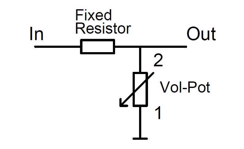 Circuit: volume potentiometer with fixed resistor